A highly customizable RGB controller implementation for Arduino
I recently decided that I needed to add some color to my workspace, but didn’t want to just use any off-the-shelf RGB controller. My first thought was to use an Arduino to control some RGB strips, but I didn’t want to have to to open the Arduino IDE and modify the firmware every time I wanted to change the program.
This desire eventually escalated to implementing a virtual machine on top of the Arduino with an application-specific instruction set designed to easily manipulate LEDs.
For the impatient reader, here’s the Github link.
Controller build
Though I did my initial testing with an Arduino Uno, I chose to go with 16MHz Pro Micros (like this one available from Sparkfun) for the actual build in order to keep the footprint small. Other than that, the supporting circuitry is dependent on the application. I’ve deployed two controllers: one inside my PC, and one for backlight behind my monitors. The setup I’m using for the PC is the simplest, so I’ll explain that one first.
The controller inside my PC is driving an SK9822-based RGB strip, so it only needs a 5V supply. Given that it’s inside a PC, there is easy access to 5V via a Molex connector from the PSU. Therefore, I’ve used that to power both the Arduino and the RGB strip. The controller module was built by soldering two female header rows to a proto board to accept the Arduino, wiring the Molex to the RAW and GND pins, and attaching a JST socket to the data, clock, and power pins. It ended up fitting nicely in the back of my case and I was able to secure it with a Velcro strap.
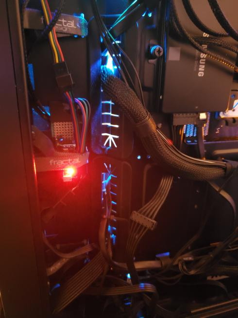
(Sorry, I forgot to take a better photo before installing it.)
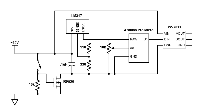
The controller for my monitor backlight is a bit more involved. For this application, wanted an on/off switch as well as a few potentiometer inputs to control the color of the strip. It’s running a WS2811 strip that takes 12V input, but I still needed a 5V reference and I didn’t want to have to keep the Arduino connected over USB. Therefore, I included a voltage regulator to step down the 12V from the strip’s power supply and a MOSFET to handle the on/off capability (since I didn’t expect the latching pushbutton switch I was using to be rated for much current).
The result was still a reasonable size and fit nicely into a decently sized project box, with just the barrel jack for the 12V and a JST connector for the strip protruding from opposite sides.
Since the circuit was a bit involved for me (having little to no experience doing such things), I drew up a schematic first.
I then prototyped the design on a breadboard.
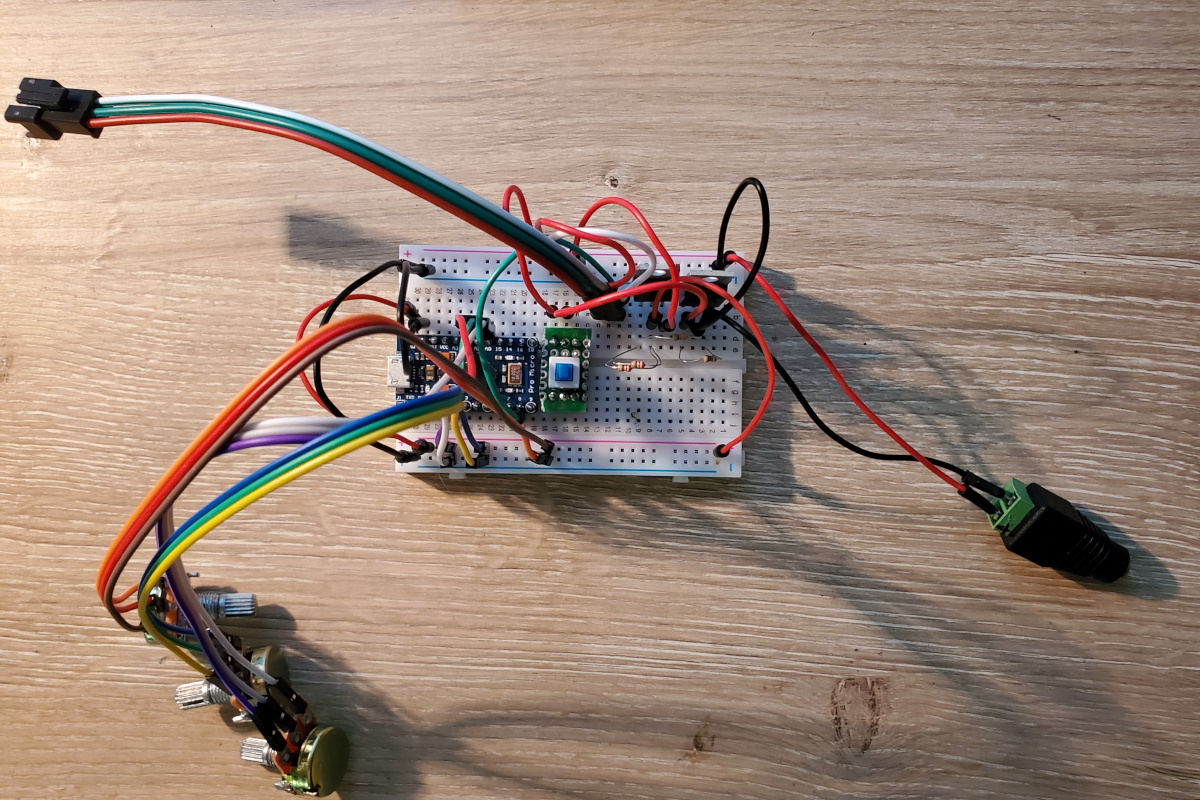
I tested it out and everything worked smoothly. I decided to leave out the decoupling capacitor depicted in the schematic as I found it wasn’t necessary.
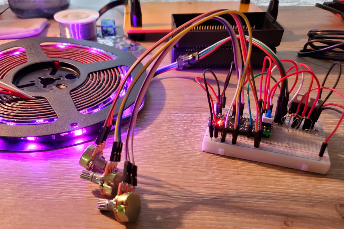
For the final build, I ended up placing the potentiometers and the power switch on their own boards, connecting them to the main board with some jumpers.
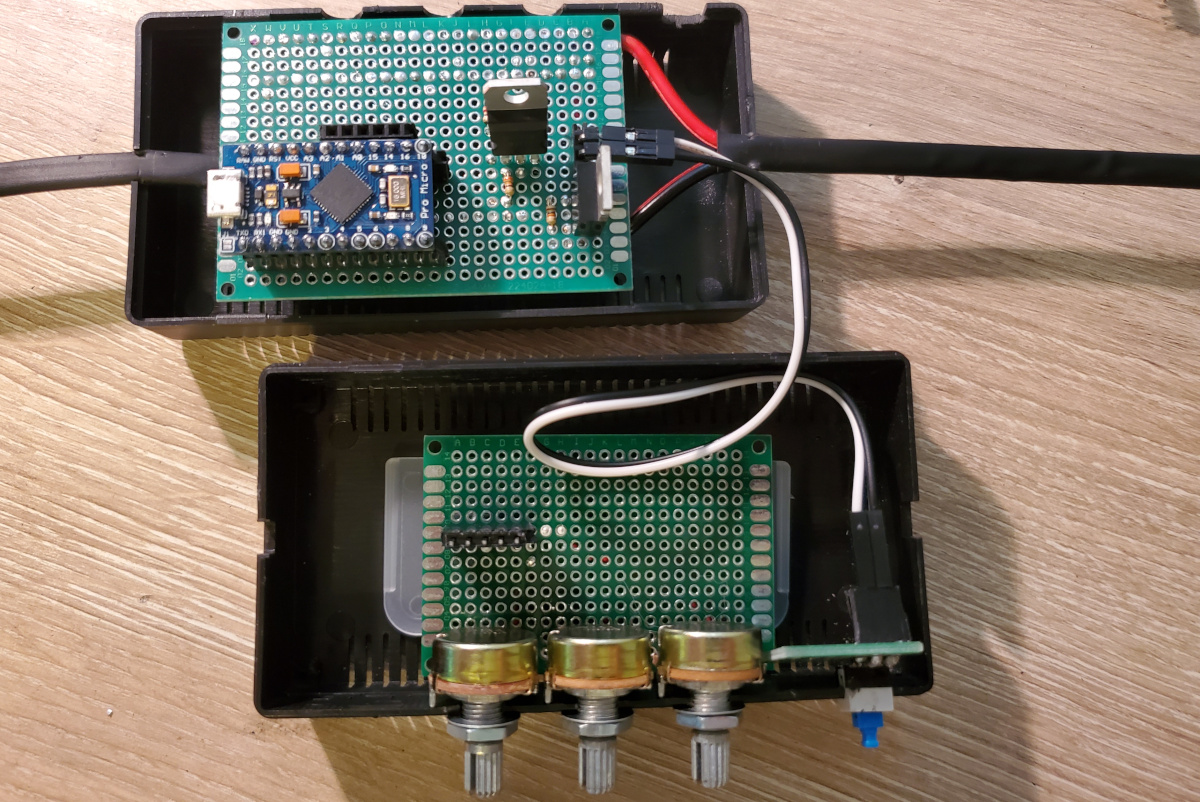
Testing it out prior to closing up the case, everything still worked as intended.
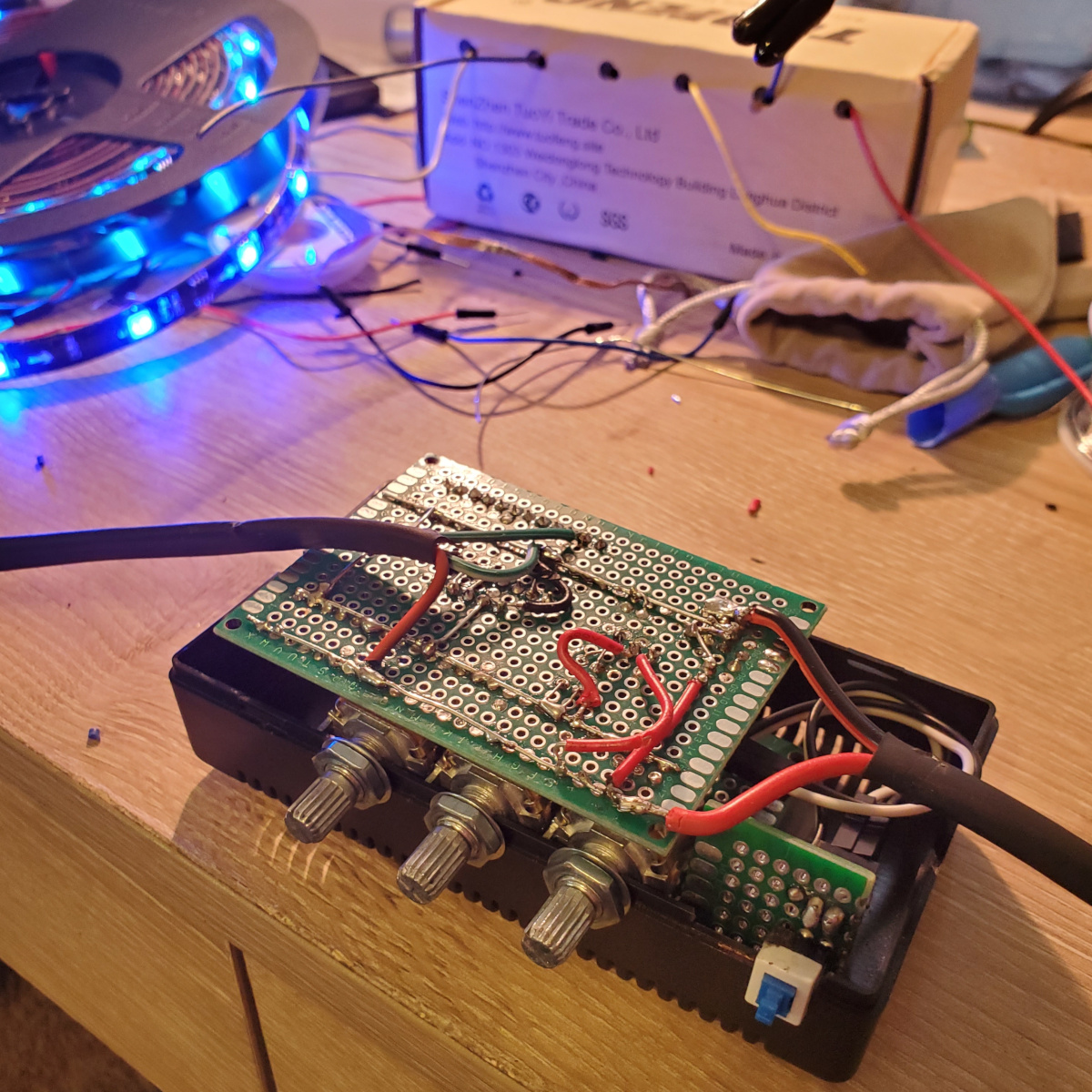
(Excuse the assorted debris on my workbench.)
For completeness, the final product:

Virtual machine
As I mentioned, the RGB controller itself is implemented in a virtual machine. It’s an 8 bit machine with 15 general purpose registers, and otherwise unremarkable except for a few special instructions for analog input, RGB output, and HSV-to-RGB color space conversion. I wrote an assembler for the machine in Python so I could write code with mnemonics instead of manually constructing bytecode.
The program memory of the VM persists in the EEPROM of the Arduino and is read into RAM at startup. It can be reprogrammed over a simple serial protocol.
The VM doesn’t have function calls (though there is branching) or any form of data memory; instead, programs only operate via I/O and registers. This was my first time implementing a virtual machine, and I wanted to keep it simple.
Drivers
The VM uses three instructions to interact with RGB devices through a set of drivers that have been implemented in the firmware. Namely, there’s an init instruction to activate a
driver, a write instruction to store an RGB value to a buffer, and a send instruction to activate the buffered values.
I’ve implemented three drivers: a simple PWM-based driver for analog RGB, a driver for the WS281x family of RGB chips, and a driver for the APA102 family of RGB chips.
Of the three, the WS281x driver was the most challenging, as it involved bitbanging the control signal with precise timings. Writing simple C or C++ code would not have met the timing constraints, thus necessitating the use of inline assembly. I found a few implementations online, but they were all designed to have a hardcoded pin number known at compile time. Since I wanted my driver to have the flexibility to choose an arbitrary pin, or even run multiple strips simultaneously, I needed to relearn AVR assembly and modify the code to use a non-constant value. Other than that, everything went pretty smoothly.
The send instruction ended up being implemented as follows:
// get the IO port number for the requested pin
const uint8_t PORT_NUM = digitalPinToPort(driver->arg);

// create a mask to enable toggling the correct pin
const uint8_t PORT_MASK = digitalPinToBitMask(driver->arg);

// get the pointer to the IO port register
volatile uint8_t *PORT = portOutputRegister(PORT_NUM);

// disable interrupts to allow for precise timing
cli();

// delay to trigger "data latch"
const uint32_t t = micros();
while ((micros() - t) < 50L) {}

// pointer to the data buffer
volatile uint8_t *p = (uint8_t *)driver->buffer;

// get the first value (subsequent values will be fetched in the asm)
volatile uint8_t val = *p++;

// apply PORT_MASK to get the register value for the high/low states
volatile uint8_t high = *PORT | PORT_MASK;
volatile uint8_t low = *PORT & ~PORT_MASK;

// tmp register will swap between high and low when need be
volatile uint8_t tmp = low;

// the number of bits remaining in the current byte
volatile uint8_t nbits = 8;

// length of the output buffer
volatile uint16_t nbytes = 3 * driver->ptr;

asm volatile("nextbit:\n\t"
            "st %a0, %1\n\t"    // store high
            "sbrc %2, 7\n\t"    // don't set tmp high if next bit zero
            "mov  %4, %1\n\t"   // otherwise, do
            "dec  %3\n\t"       // decrement bit counter
            "nop\n\t"           // nop for keeping timing
            "st   %a0, %4\n\t"  // write tmp to the IO register
            "mov  %4, %5\n\t"   // next, we'll set the line low
            "breq nextbyte\n\t" // load the next byte if done with last
            "rol  %2\n\t"       // otherwise, rotate in the next bit
            "rjmp .+0\n\t"      // nop for keeping timing
            "st %a0, %5\n\t"    // set the line low
            "rjmp .+0\n\t"      // nop for keeping timing
            "nop\n\t"           //
            "rjmp nextbit\n\t"  // send the next bit
            "nextbyte:\n\t"
            "ldi  %3, 8\n\t"    // reset the bit counter
            "ld   %2, %a6+\n\t" // load the next byte
            "st %a0, %5\n\t"    // set the line low
            "rjmp .+0\n\t"      // nop for keeping timing
            "nop\n\t"           //
            "dec %7\n\t"        // decrement the byte counter
            "brne nextbit\n\t"  // loop if there are more bytes
            ::"e"(PORT), "r"(high), "r"(val), "r"(nbits), "r"(tmp),
              "r"(low), "e"(p), "w"(nbytes));

// re-enable interrupts
sei();

// clear the output buffer
driver->ptr = 0;
The assembly seen here is derived from this post. Note that the chip expects a GRB byte order. To keep the assembly simple, the reordering is handled in the write instruction.
The APA102 driver was much easier to implement, since it uses a clock signal and thus does not rely on precise timings.
const uint8_t clock = driver->arg, data = driver->arg + 1;

digitalWrite(data, LOW);

// start frame
apa102_byte(clock, data, 0);
apa102_byte(clock, data, 0);
apa102_byte(clock, data, 0);
apa102_byte(clock, data, 0);

// send data for each entry in the buffer
for (int i = 0; i < driver->ptr; ++i) {
    // header (currently hardcoded max brightness)
    apa102_byte(clock, data, 0xff);

    // the chip expects b, g, r byte order
    apa102_byte(clock, data, driver->buffer[i].b);
    apa102_byte(clock, data, driver->buffer[i].g);
    apa102_byte(clock, data, driver->buffer[i].r);
}

// end frame
for (int i = 0; i < driver->ptr; ++i) {
    apa102_byte(clock, data, 0x00);
}

// leave the line low when done
digitalWrite(data, LOW);

driver->ptr = 0;
The apa102_byte call simply sets the data line to the correct state then toggles the clock line high then low.
Instruction set
The VM implements 19 mnemonic instructions. In reality, the branch instructions are all implemented under a single opcode followed by a mode flag which determines whether and how to inspect the flag register.
| Mnemonic | Operands | Description |
|---|---|---|
| nop | [imm] | no operation – if imm specified and nonzero, sleep 2^(imm-1) ms |
| set | rdst (rsrc|imm) | load register rdst from rsrc or immediate |
| add | rdst (rsrc|imm) | add to rdst from rsrc or immediate |
| mul | rdst (rsrc|imm) | multiply rdst by rsrc or immediate |
| div | rdst (rsrc|imm) | divide rdst by rsrc or immediate |
| mod | rdst (rsrc|imm) | modulo rdst by rsrc or immediate |
| cmp | r0 (r1|imm) | compare r0 to r1 or imm and store the result in flags |
| goto | address | move the instruction pointer to address |
| brne | address | move the ip to address if last comparison was not equal |
| breq | address | move the ip to address if last comparison was equal |
| brlt | address | move the ip to address if last comparison was less than |
| brle | address | move the ip to address if last comparison was less or equal |
| brgt | address | move the ip to address if last comparison was greater than |
| brge | address | move the ip to address if last comparison was greater or equal |
| hsv2rgb | rh rs rv | convert hsv values in registers to rgb (in place), each of hsv in [0, 255] |
| init | immd immc [immf] | initialize output channel immc with driver number immd and optional flags immf |
| write | rr rg rb immc | buffer rgb value from registers on output channel immc |
| send | immc | activate the buffered output of immc |
| input | rdst immpin | load rdst with the value from the analog pin numbered by the immediate |
Implementation
Instructions
Instructions for rgbvm are of varying size. Starting with a 4-bit opcode is the only thing they have in common.
struct rgbvm_instruction {
    enum rgbvm_opcode opcode : 4;
};
Each class of instruction then has its own derived structure. For brevity, I’ll only include the structures of the arithmetic and driver interaction instructions, but this should be sufficient to provide a general idea of the structure of the bytecode.
struct rgbvm_arithmetic_instruction {
  enum rgbvm_opcode opcode : 4;
  enum rgbvm_reg dst : 4;
  enum rgbvm_reg src : 4;
  uint8_t padding : 4;
  uint8_t imm[];
};

struct rgbvm_init_instruction {
  enum rgbvm_opcode opcode : 4;
  enum driver_type driver : 4;
  uint8_t channel : 2;
  uint8_t arg : 6;
};

struct rgbvm_write_instruction {
  enum rgbvm_opcode opcode : 4;
  enum rgbvm_reg srcr : 4;
  enum rgbvm_reg srcg : 4;
  enum rgbvm_reg srcb : 4;
  uint8_t channel : 2;
  uint8_t padding : 6;
};

struct rgbvm_send_instruction {
  enum rgbvm_opcode : 4;
  uint8_t channel : 2;
  uint8_t padding : 2;
};
Arithmetic instructions have an optional immediate, thus the 0-length array at the end of that structure.
VM state and execution
The structure describing the state of the VM is simple:
struct rgbvm_state {
  // instruction pointer
  uint16_t ip;

  // length of code segment
  uint16_t ip_max;

  // 15 general purpose registers
  uint8_t reg[15];

  // flag register
  int flag;

  // output buffers
  struct rgbvm_driver outputs[4];
};
In setup, the first two bytes of EEPROM are read to determine the length of the code segment (thus determining ip_max).
const uint16_t code_len = (EEPROM.read(0) << 0) | (EEPROM.read(1) << 8);
The bytecode is then read from EEPROM into RAM:
for (int i = 0; i < code_len; ++i) {
    s.code[i] = EEPROM.read(i + sizeof(uint16_t));
}
In loop, when executing code, the instruction at the current instruction pointer is passed to
rgbvm_apply.
rgbvm_apply(delay, &s.vm, (const rgbvm_instruction *)&s.code[s.vm.ip]);
We pass a pointer to the delay function so the VM can call it when a nop instruction
with a nonzero argument is encountered.
The implementation of rgbvm_apply revolves around a switch on the opcode of the current instruction. For example, the arithmetic instructions are handled as follows.
case RGBVM_OP_SET:
case RGBVM_OP_ADD:
case RGBVM_OP_MUL:
case RGBVM_OP_DIV:
case RGBVM_OP_MOD:
case RGBVM_OP_CMP: {
    uint8_t *dest;
    uint8_t src;
    uint8_t size;
    rgbvm_arith_op_impl op;
    rgbvm_decode_arithmetic(vm,
                            (struct rgbvm_arithmetic_instruction *)inst,
                            &dest, &src, &op, &size);
    op(vm, dest, src);
    rgbvm_increment_ip(vm, size);
    return RGBVM_STATUS_OK;
}
These instructions are all implemented as functions taking arguments of a pointer to the VM state, a pointer to the destination operand, and the value of the source operand. The rgbvm_decode_arithmetic function is decoding the operands and setting the corresponding pointer and value, as well as setting a function pointer to the instruction implementation and determining the length of that instruction.
Decoding the destination operand simply involves returning a pointer to the correct register, while decoding the source operand also has logic handling immediate values.
int rgbvm_decode_val(struct rgbvm_state *vm, const enum rgbvm_reg reg,
                     const struct rgbvm_arithmetic_instruction *inst,
                     uint8_t *dest, uint8_t *imm_flag) {

    if (reg == RGBVM_REG_IM) {
        *dest = inst->imm[0];
        *imm_flag = 1;
        return 0;
    }

    *imm_flag = 0;
    const uint8_t *src = rgbvm_decode_reg(vm, reg);
    *dest = *src;
    return 0;
}
The imm_flag allows rgbvm_decode_arithmetic to determine the length of the instruction and is used to increment the instruction pointer appropriately.
The instructions for communicating with the drivers rely on a set of functions with a common interface for initializing, writing, and outputting data.
typedef void (*driver_write)(struct rgbvm_driver *, const uint8_t,
                             const uint8_t, const uint8_t);
typedef void (*driver_init)(struct rgbvm_driver *, const uint8_t arg);
typedef void (*driver_send)(struct rgbvm_driver *);
Each driver defines an init function which sets pointers to write and send within the VM’s outputs array.
The corresponding instructions are implemented as follows.
case RGBVM_OP_INIT: {
    const struct rgbvm_init_instruction *i =
        (const struct rgbvm_init_instruction *)inst;
    driver_init init = get_driver(i->driver);
    init(&vm->outputs[i->channel], i->arg);
    rgbvm_increment_ip(vm, 2);
    return RGBVM_STATUS_OK;
}
case RGBVM_OP_WRITE: {
    const struct rgbvm_write_instruction *i =
        (const struct rgbvm_write_instruction *)inst;
    const uint8_t *r = rgbvm_decode_reg(vm, i->srcr);
    const uint8_t *g = rgbvm_decode_reg(vm, i->srcg);
    const uint8_t *b = rgbvm_decode_reg(vm, i->srcb);
    driver_write fn = vm->outputs[i->channel].write;
    fn(&vm->outputs[i->channel], *r, *g, *b);
    rgbvm_increment_ip(vm, 3);
    return RGBVM_STATUS_OK;
}
case RGBVM_OP_SEND: {
    const struct rgbvm_send_instruction *i =
        (const struct rgbvm_send_instruction *)inst;
    driver_send fn = vm->outputs[i->channel].send;
    fn(&vm->outputs[i->channel]);
    rgbvm_increment_ip(vm, 1);
    return RGBVM_STATUS_OK;
}
The drivers implement write by storing the r, g, b values in the output channel’s buffer; send then implements the protocol for sending this data to the LEDs.
The branch instructions follow a similar pattern to the arithmetic instructions. These and the remaining instructions’ implementations are omitted for brevity
Serial protocol
The state machine handling bytecode updates from serial ingests a single byte at a time.
if (Serial.available() > 0) {
    proto_msg msg;
    if (proto_state_machine_ingest(&s.vm, s.code, &s.psm, Serial.read(),
                                   &msg, write_eeprom) {
        Serial.write((uint8_t)msg);
    }
}
The return of proto_state_machine_ingest indicates whether msg has been modified, thereby
indicating a response that should be written to serial.
The state machine itself supports four states:
enum proto_state {
  PROTO_STATE_INIT,
  PROTO_STATE_SIZEH,
  PROTO_STATE_SIZEL,
  PROTO_STATE_CODE
};
Initially, it is in the INIT state. When in any other state, the VM pauses execution of bytecode until the transaction is completed.
The state machine first expects a HELLO message from the peer; upon receipt it transitions to the SIZEL state, indicating that it is ready to receive the low byte of the length of the bytecode.
case PROTO_STATE_INIT: {
    if (byte == PROTO_MSG_HELLO) {
        psm->state = PROTO_STATE_SIZEL;
        *res = PROTO_MSG_OK;
        return 1;
    }
    *res = PROTO_MSG_ERR;
    return 1;
}
After that byte is received, the state is set to SIZEH, indicating that the high byte of the bytecode length is expected. After receiving that, the state machine then transitions to CODE, where it stays until the specified number of bytes are received.
case PROTO_STATE_SIZEL: {
    ((uint8_t *)&vm->ip_max)[0] = byte;
    psm->state = PROTO_STATE_SIZEH;
    return 0;
}
case PROTO_STATE_SIZEH: {
    ((uint8_t *)&vm->ip_max)[1] = byte;
    psm->state = PROTO_STATE_CODE;
    psm->offset = 0;
    *res = PROTO_MSG_OK;
    return 1;
}
The serial ingest implementation writes the bytecode directly to the VM’s code
array in order to save memory. After receiving the full bytecode, the state machine returns
to INIT and returns an OK message.
After receiving a bytecode update, a callback is invoked to write the new bytecode to EEPROM, then the VM state is updated with the new length of the code segment and the instruction pointer is reset to zero.
case PROTO_STATE_CODE: {
    code[psm->offset++] = byte;
    if (psm->offset == vm->ip_max) {
        cb(psm);
        vm->ip = 0;
        psm->state = PROTO_STATE_INIT;
        *res = PROTO_MSG_OK;
        return 1;
    }
    return 0;
}
Because writing the bytecode to EEPROM is delayed until after receiving the full stream, the device can simply be reset to revert back to the old code if an error occurs in transmission.
Outcome
This was a challenging project for me because it involved a lot of new things. However, I learned a lot and it payed off. After about a week of working on this for a couple of hours every day, I’ve finally got a colorful battlestation.

The source code for this project is available on Github.