Revised smart doorbell adapter circuit
In a previous post, I described issues encountered when integrating the Unifi G4 Doorbell with a digital chimebox. I designed an adapter circuit, and it worked for a few months; however, eventually I started encountering problems and upon further investigation discovered that some of the assumptions I made about the behavior of the Unifi chime adapter module were incorrect. With this new information, I designed a new circuit which is actually simpler and should be more reliable.
After about five months in operation, the circuit I detailed in the earlier post started emitting a buzzing sound. The relay contacts were in fact vibrating, but why? The first stage of this investigation involved hooking up the “output” leads from the module to my oscilloscope.
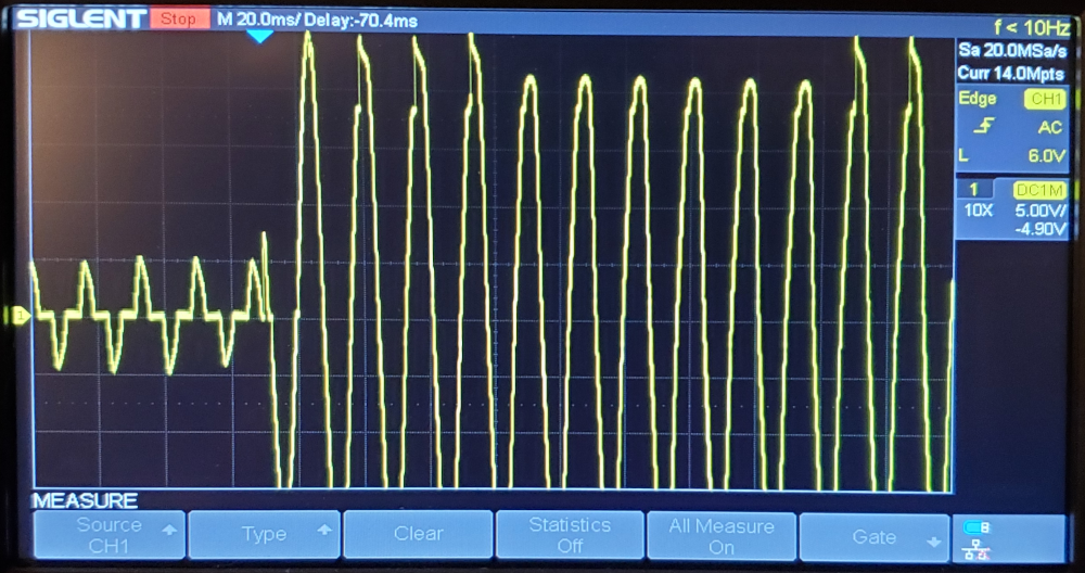
To the left of the trigger, we can see some bizarre modulated AC signal. This represents the “idle” state, where the doorbell has not been pressed. The RMS voltage of this was too low for my cheap multimeter to register, and thus I had incorrectly thought it was a zero volt output. While initially there were no consequences for this error, after some time apparently the relay I chose decided this was enough voltage to cause it to oscillate.
This discovery also made me realize that the characterization of these two leads as “outputs” was incorrect. I popped open the chimebox module and discovered that there are really only two terminals inside; in fact, the two pairs of leads sticking out of the box were mapped two these two terminals in parallel. That is, in the intended deployment scenario, this module sits parallel to the chimebox.
I didn’t take time to fully reverse engineer the board, but identified a comparator and a relay. Nothing else in here can effect any logic. Something strange is going on. Time for more fun with the scope.
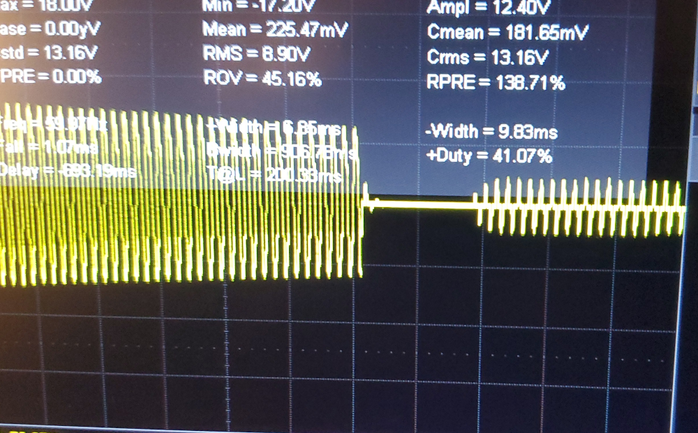
Here we can see the behavior when the ring period ends. There is a zero-volt period prior to the idle signal resuming. My best guess at this point is that the adapter module clamps the voltage across the chime low (yielding that idle signal), then when it detects a voltage increase effected by the doorbell itself, triggers the relay to stop clamping. The doorbell later opens the circuit, resetting the module, then the idle resumes.
I came up with a few ideas to filter out the idle stage (RC filter, comparator, attiny85) but landed on a fairly simple design that I think should work reliably.
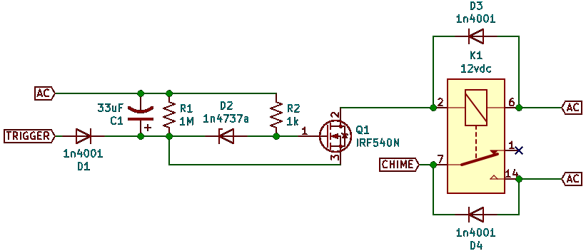
Now armed with some knowledge of how the Unifi chime module works, the new adapter board can be designed with only three terminals: one for each lead of the Unifi module, and one connecting to the chimebox. The two module leads are identified in the schematic as “AC,” connecting back to the transformer, and “TRIGGER,” connecting to the doorbell.
Using a half-bridge (single diode) rectifier (D1) and some smoothing (C1), we can get an estimate of the current voltage on the TRIGGER line, and rely on a zener diode (D2) to determine when this passes the activated threshold. The zener is connected to the gate of a mosfet (Q1), pulled low; the mosfet can then switch the relay (K1). When the relay is open, another half-bridge (D4) provides the idle supply to the chimebox. A flyback diode (D3) has also been added across the coil of the relay.
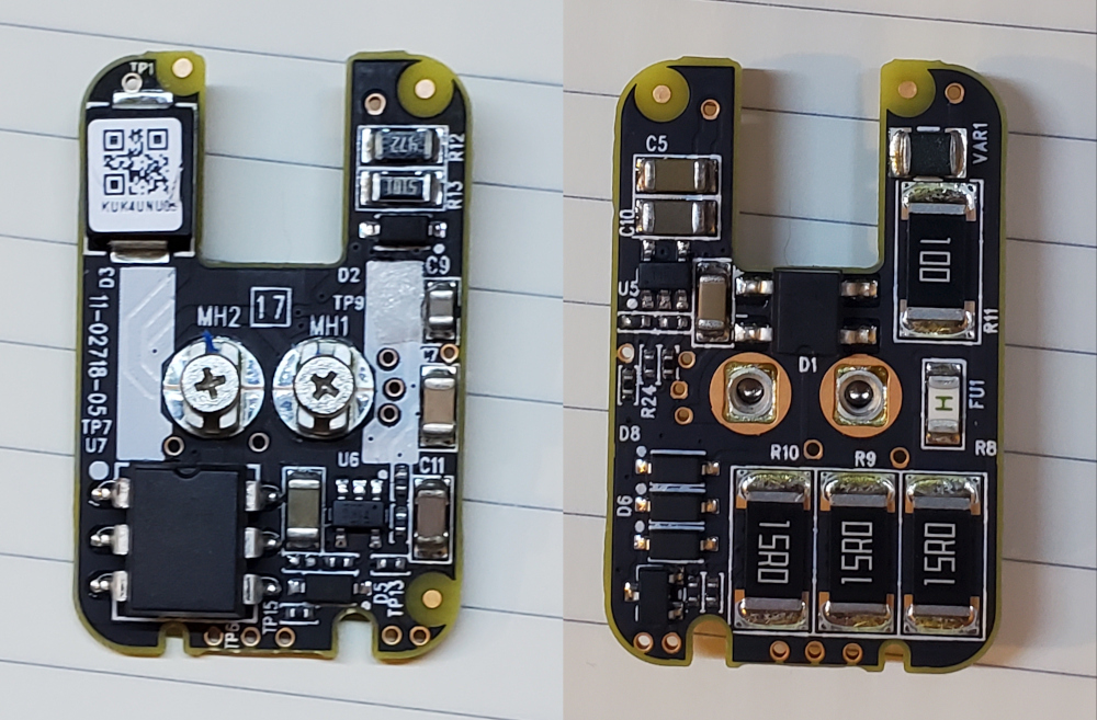
After some testing, this circuit seemed to work, so I put something together on protoboard.
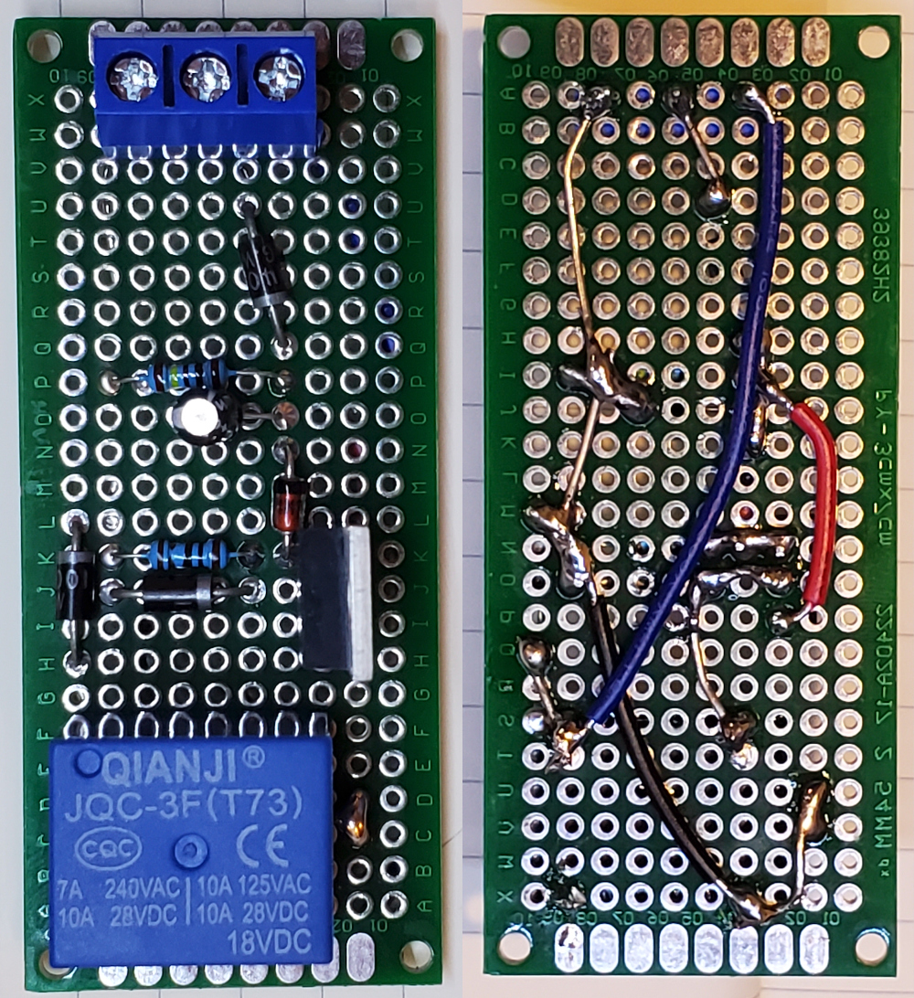
The first terminal connects to the transformer (AC), the second to the doorbell (TRIGGER), and the third to the chime. The other terminal of the chime then connects back to the transformer (on the opposite side of the circuit).
Note that the reverse face of the board has been flipped as to correspond directly to the front.